Design · 2025
SolidWorks Practice.
Transitioning from Onshape to SolidWorks
- Role
- Self Development
- Year
- 2025
Summary
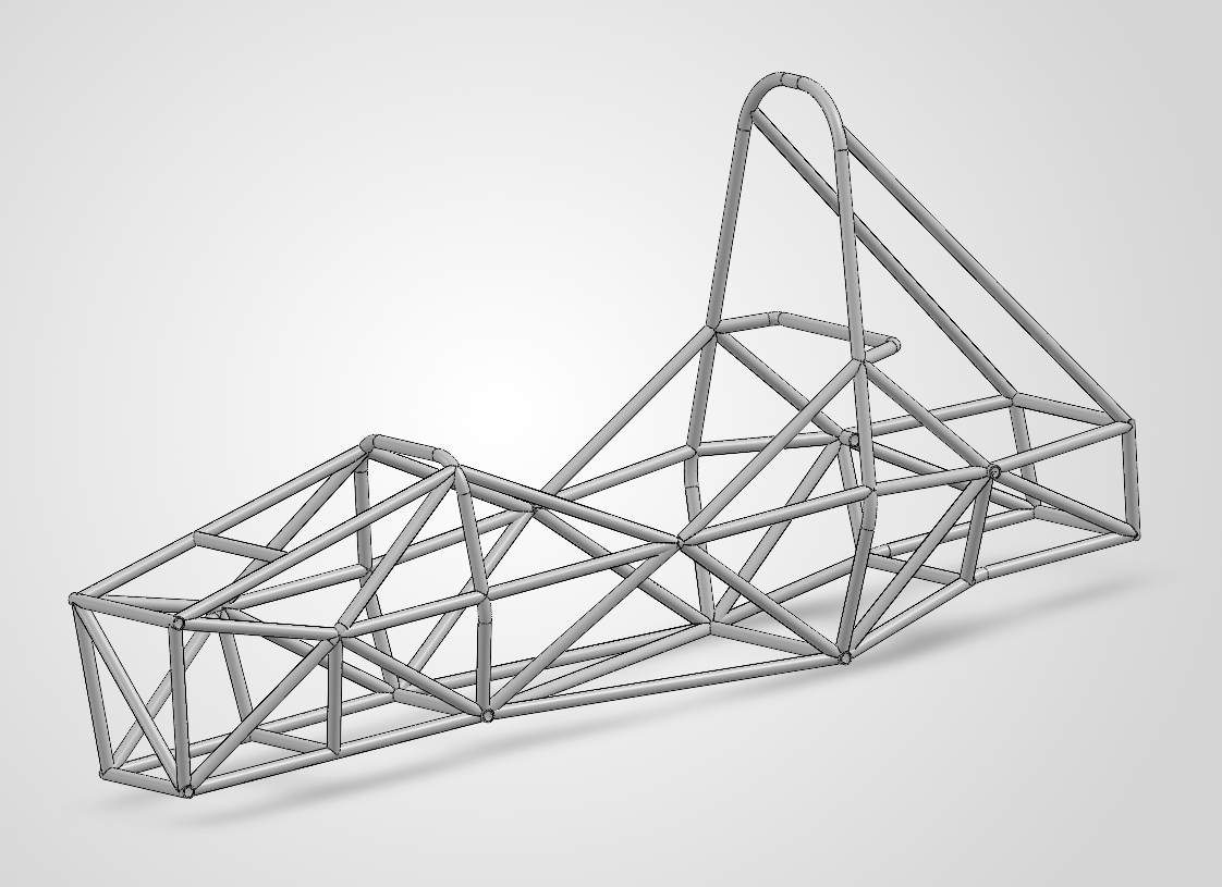
After four years of working primarily in Onshape, I started learning SolidWorks to prepare for future engineering opportunities where it is commonly used. To make the transition more practical, I decided to design an SAE style race car assembly consisting of a chassis and suspension. This gave me a project to work through SolidWorks' workflow while applying mechanical design concepts I already understood from robotics.
I used the chassis and suspension as a way to learn SolidWorks while designing a complete vehicle assembly. I gained experience with SolidWorks' weldments, custom weldment profiles, and 3D sketches while also learning more about suspension geometry and variables such as camber. The project helped me understand how SolidWorks approaches assemblies and design workflows differently from the Onshape workflow I was used to.
Highlights
- Independent modeling practice
- Learned custom weldmetns profiles
- Practiced 3D sketching
Breakdown
How it works.
Master Sketch
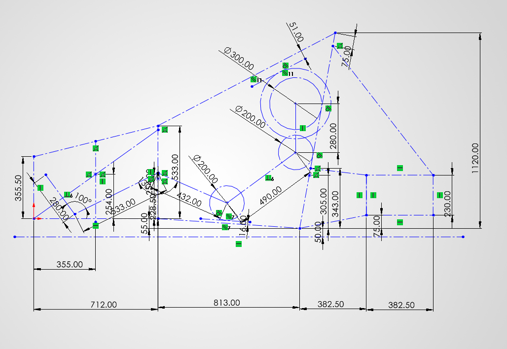
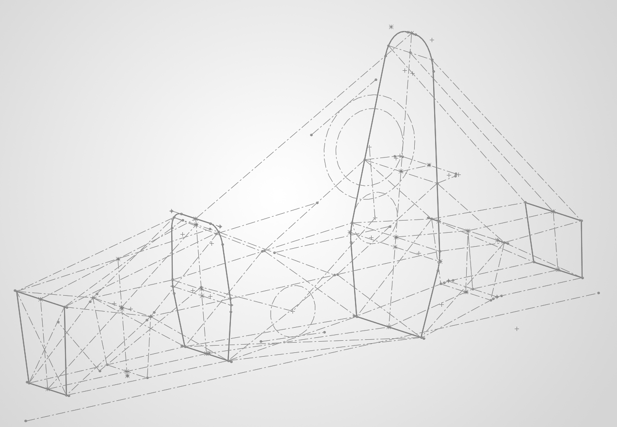
To begin the chassis, I created a master sketch with a driver model to establish the overall ergonomics of the car. Once the side profile had the proportions I wanted, I added cross sections at the locations where the outer edges of the frame would run. I then added braces between the main tubes to improve the structure while keeping the frame layout simple.
Weldments
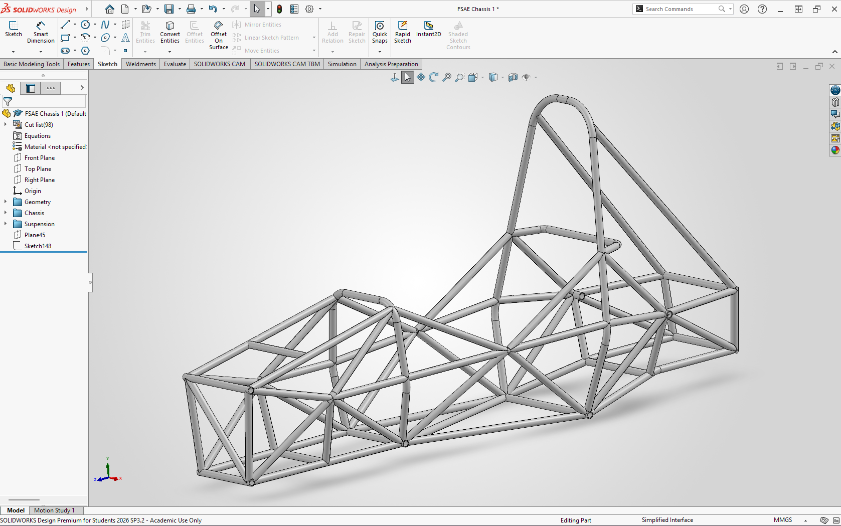
I created a custom weldment profile and used SolidWorks Weldments to turn the 3D sketches into structural tubes. The tubes had to be trimmed using weldment corner treatment and trim tools so that they did not interfere with each other and could be manufactured. I tried to avoid difficult geometries such as four way tube intersections and instead designed the frame around simpler joints that would be easier to fabricate.
Suspension Geometry
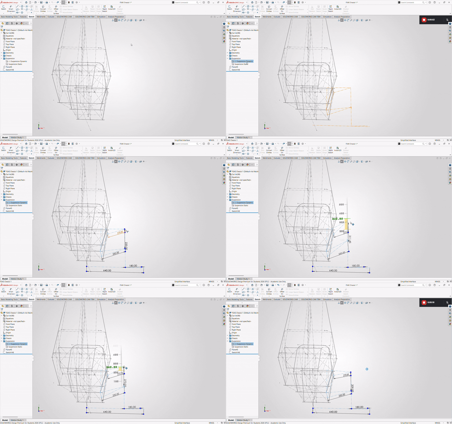
After establishing the chassis hardpoints, I began working on the suspension geometry. I used this part of the project to learn the major components of a suspension system and how variables such as camber affect handling and cornering. From there, I developed a geometry intended to keep the car level relative to the ground while naturally changing camber as the suspension moved through a turn.
Upright Design
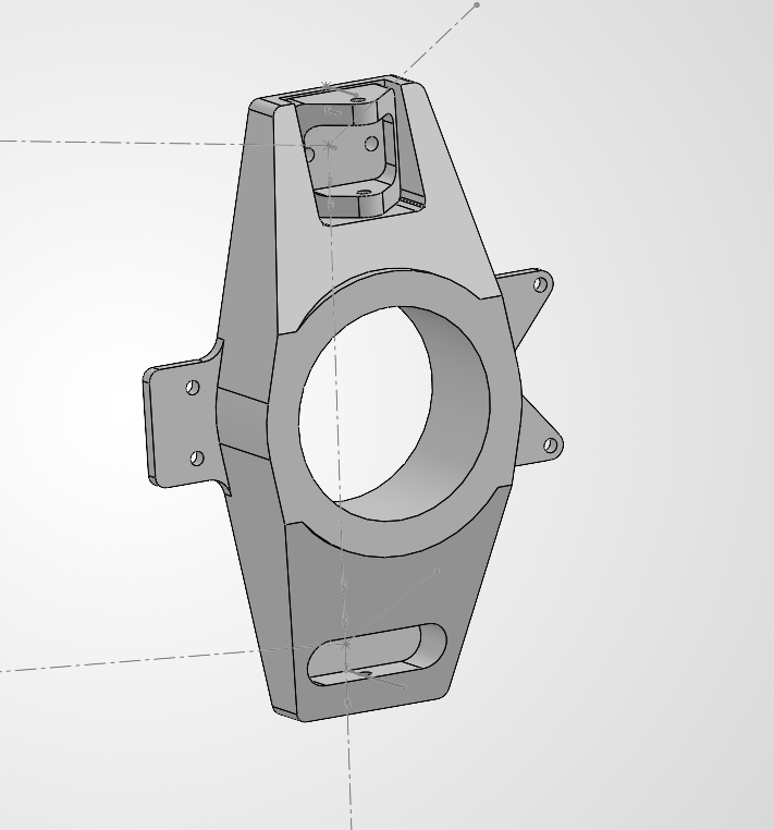
I was not able to finish the suspension master sketch, but I completed a rough version of the geometry and began designing a simple upright. I used the upright to practice SolidWorks part modeling and design for manufacturing, applying the same approach I use in robotics by considering how the part would actually be machined and assembled rather than only focusing on the CAD geometry.
Gallery
Inside the build.
Skills Gained
What I sharpened.
Useful Links
Dig deeper.
Keep going